Every substation, solar plant and telecom tower needs an earthing system, and every earthing design starts with one number: how well the ground conducts electricity. Electrical engineers ask us for that number all the time, usually with a short deadline and a site that is nothing but dry sand and rock. This post explains how we measure soil resistivity on Saudi sites, what can go wrong, and what the designer should receive at the end.
Why the earthing designer needs measured values
An earthing grid has to carry fault current safely into the ground and keep touch and step voltages within safe limits. The resistance of that grid depends directly on the resistivity of the soil around it. In much of the Kingdom the ground is dry, sandy or rocky, and resistivity can be very high, often hundreds to thousands of ohm-metres near the surface. If the designer guesses low, the grid ends up undersized. If they guess high to be safe, the project pays for copper, rods and chemical backfill it may not need.
A measured profile removes the guesswork and gives the designer real layer values to work with.
How the test works
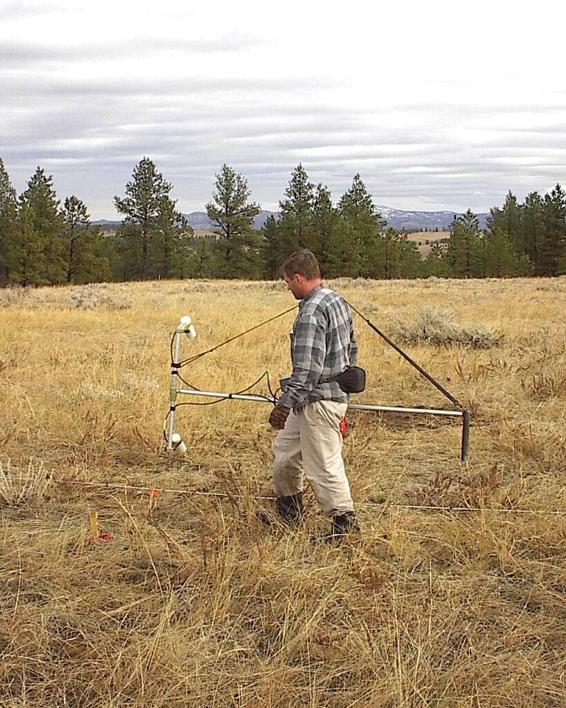
We use the four-pin method. Four steel electrodes are driven in a straight line. A current is passed between the two outer pins and the voltage is measured between the two inner pins. The instrument reports a resistance, and from the pin spacing we calculate the apparent resistivity.
For the Wenner arrangement, where all four pins are equally spaced at a distance a, the formula is simple: apparent resistivity = 2 × π × a × R. Readings at a short spacing describe the shallow ground. As the spacing increases, the current travels deeper and the reading reflects deeper layers. Repeating the test at a series of spacings, for example 1, 2, 3, 5, 10, 15, 20 and 30 m, gives a curve of resistivity against spacing that the designer can turn into a soil model.
On large plots we sometimes use the Schlumberger arrangement instead. The inner pins stay close together while only the outer pins move, which saves time and gives a stronger signal at wide spacings.
Laying out the traverses
One line of readings is rarely enough. We normally run at least two traverses at right angles at each test location, so a buried feature or a change in ground along one direction does not distort the whole result. A villa or small building may need a single location. A substation or a solar plant usually needs several locations spread across the footprint of the earthing grid, because ground conditions can change across a few hundred metres.
Lines are kept well away from buried pipes, cables, fences and existing earthing, because metal close to the line short-circuits the current and gives readings that are far too low. On developed sites we check for services first with a cable locator or a GPR survey before we set out the pins.
Problems we see on Saudi sites
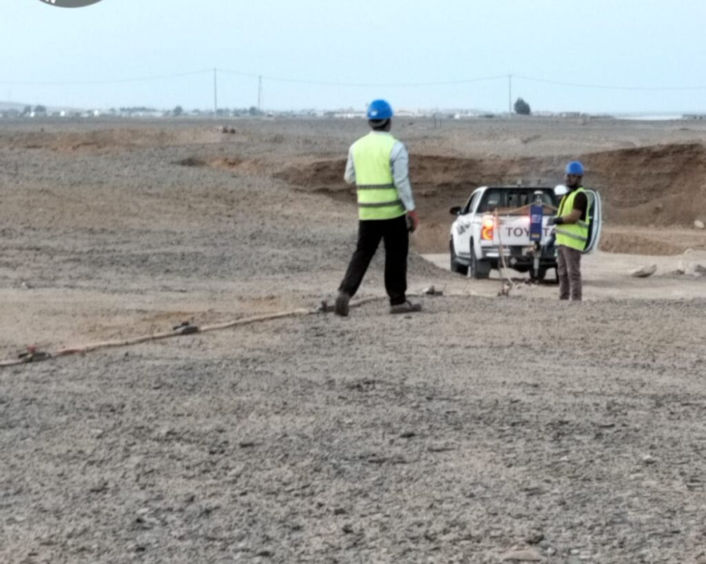
- Dry surface sand. Contact between the pin and the ground can be very poor. We water the pins, sometimes with a little salt water, and check the contact before each reading.
- Rock or caliche near the surface. Pins cannot always be driven deep enough. We note the depth achieved and, where needed, shift the line a few metres.
- Season. Dry summer ground reads higher than the same ground after rain. We record the conditions on the day so the designer can allow for it.
- Odd readings. If one value does not fit the curve, we repeat it on the spot rather than explain it away in the office.
Point tests or a resistivity section?
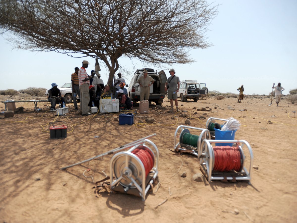
The four-pin test gives a profile at each location, which is what most earthing designs need. Where the ground is clearly layered or changes across the site, or along long transmission and pipeline routes, an electrical resistivity tomography (ERT) survey gives a continuous section instead of a handful of points. The two methods use the same physics but answer slightly different questions, and on bigger projects we often use both.
What the designer should receive
- Field sheets with spacing, measured resistance and apparent resistivity for every reading
- Resistivity against spacing curves for each traverse
- A two-layer or multi-layer soil model where the data supports it
- A location plan of all traverses with coordinates
- Notes on weather, ground conditions and anything that may have affected the readings
Soil resistivity is not the same as an earth resistance test. The resistivity test measures the ground before design. An earth resistance (fall-of-potential) test checks a finished electrode or grid after it has been installed. If you are not sure which one your specification asks for, send it to us and we will tell you.
Frequently asked questions
How many test locations does a substation need?
It depends on the size of the earthing grid and how uniform the ground is. Small sites may need one location with two traverses. Substations and solar plants normally need several locations across the grid area.
How long does a soil resistivity test take?
A single location with two traverses can usually be completed in a few hours. Large plants with many locations take one or more days, plus time for the report.
Can you test on rocky ground?
Yes, although pin depth and contact are harder to achieve. We record the conditions and adjust the layout so the readings stay reliable.
Need soil resistivity data?
EarthScape carries out soil resistivity and earthing surveys across Saudi Arabia. Send us the site location, the plot or grid size and your design requirements through our Get a Quote page, and we will propose the number of test locations and a programme.